Sound familiar? You need to measure your component's specific region of interest, but you can't get to it. Or a digital twin might be just what you need for quality assurance. But where would it come from? And how do you do the CAD comparison if you only have a 2D image of your part? The '5 Applications on 5 Axes' online event showcases five real-world applications and the technology to solve even the most complex measurement challenges on your stamped parts, turned parts and round tools.
At first you may think that your measurements on the stamped parts, turned parts or round tools are already sufficient. This may well be true for some applications. However, you miss the CAD comparison if you think about it more carefully. A 3D representation of the entire component, which you can use for the target/actual comparison, naturally offers a much more detailed insight into your production and its limitations. In addition, the three component types stamped, turned parts and round tools often have areas that are difficult to reach with only three axes, but which play a decisive role in functionality. Of course, as a user of optical 3D technology, you are generally much less restricted than you would be with tactile methods, but a rotation and tilting unit can make your measuring work much easier. The advantages are:
+ Precise 360° measurement of complex geometries
+ Detailed analysis of intricate profiles
+ Measurement of parts from numerous angles
+ Digital twin creation
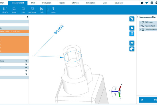
+ Target-actual comparisons with CAD data
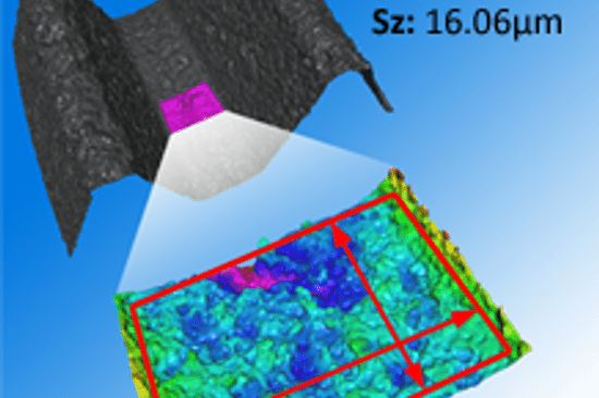
+ High precision in verifying deviations of GD&T and roughness parameters
To make one thing clear: Not only stamped parts, turned parts and round tools require comprehensive quality assurance. These applications represent an excerpt that should give you a feeling for the importance of 360° measurements.
dieSonne-web-(66)-1024x1025-200x200.jpg "Fullform measurement of a stamped part")
Stamped part (connector)
tilted by ~ 45°
to access all areas
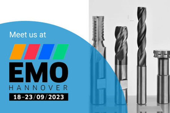
Round tools are a crucial element in machining. After all, the drill or milling cutter is the tool that has a decisive influence on the product. This results in several parameters that must be checked for quality assurance.
+ Edge Preparation
+ Angles
+ Roughness
+ Core Diameter
+ Outer Diameter
+ CAD Comparison
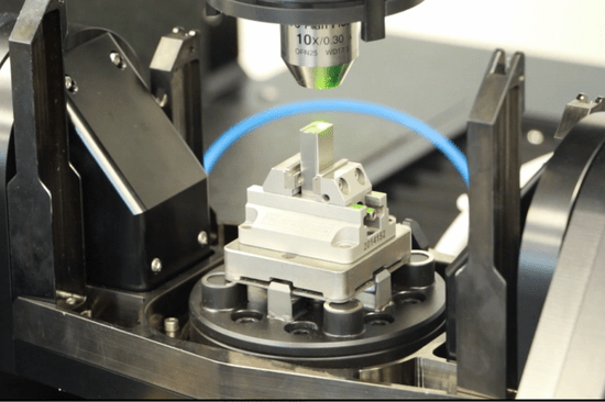
are some of the examples for which you need multiple angles. It is not only the accessibility of difficult areas on the component that makes the measurement on five axes so special. The MetMax software also performs an automated routine to detect the alignment of the round tool. The system aligns the drill or milling cutter according to the CAD. Just think about what you gain from this automatic round tool alignment: User independence, time and cost savings and a real boost in terms of precision. In this video you can see how the five-axis FocusX makes your life easier when determining the most important round tool parameters:
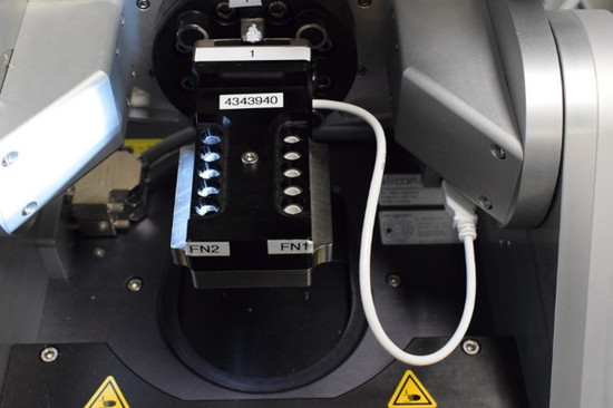
The press-fit zones of the connectors are another example of achieving difficult regions on your components. The geometry has to be fit to create a gas-tight connection without soldering. The most critical part of the press-fit zone is the tip of the small connector.
The following parameters are crucial for a perfect connection between the press-fit zone and the board:
+ Angles
+ Diameters
+ Tip Hight
+ Tip Width
The video shows you how the five axes help to evaluate the desired parameters and how high the point density of such a measurement is.
Another application from the stamped parts family is the crimp connector. It is even more complex in its overall geometry. A crimping tool is needed to create the contact. Determining the crimp tab contour and the contact area cross-sections is crucial to quality. The contour of the contact area and the crimp area also play an important functional role. Finally, we show the CAD comparison of the entire contact in the video below:
Turning produces extremely precise components. The raw material rotates on just one axis of rotation. A cutting insert, which only moves along the X-axis towards the rotating tool, removes the excess material until you have achieved the final geometry of the turned component.
The bone screw is the first application from the turned part family that we have clamped for you on the Real3DUnitX to show the advantages of measuring with five axes. We certainly don't need to explain the importance of precision in medical screws. In this video, we would rather show you which measuring method you can use to maintain the tightest tolerances for bone screws.
With bone screws, everything revolves around these parameters:
+ Radii
+ Distance
+ Angles
+ Diameter
+ Pitch
+ Hex Geometry of the head
Most turned parts are symmetrical. This results from the classic production process, which we have already briefly outlined above with the bone screw. To illustrate how much the rotation and tilting unit can simplify the measurement of random turned parts, we have created another video.
The following measurements are decisive:
+ Roughness
+ Angles
+Cylinders
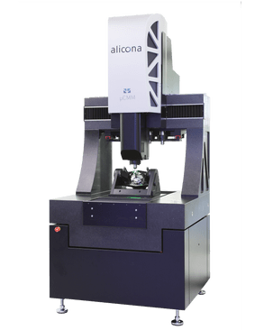
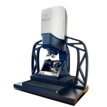
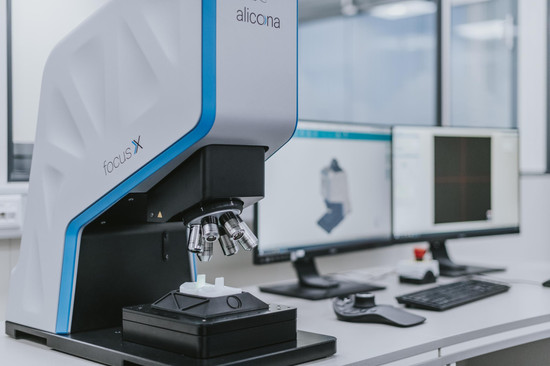
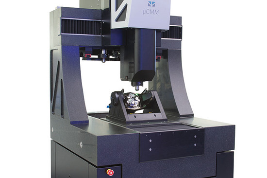
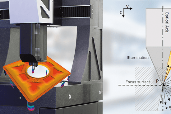
The Real3DUnitX is an extension for the FocusX. It is a connected rotation and tilting device. The FocusX itself offers three axes, X, Y and Z with a travel range of 100 x 100 x 100 mm. The two additional axes, which are obtained by rotation and tilting, allow measurements from different perspectives, which are combined to form an overall picture. Best of all, the alignment of the component is fully automated, repeatable and traceable. The FocusX is not the only measuring device that can be extended to 5 axes. Rotation and tilt units are also available for the InfiniteFocus G6 and the µCMM. See links below.

The technology of the Real3DUnitX is quickly explained: Your component is measured at various rotation angles. The single measurements are transformed into a joint coordinate system. Overlapping measurements are merged into a complete 3D data set. The operation in the software is just as simple.
The parameters that you obtain by using the rotation and tilting unit on the FocusX are more versatile than you can inspect using optical 3D measurement technology with just three axes. Do you have any of these requirements?
Then expanding your system to 5 axes is what you need.

dieSonne-web-(21)-550x366.jpg "Turbine Blade with Cooling Holes")


_Nagel-550x366.jpg)


-550x366.jpg)
dieSonne-065-868x397-550x366.jpg)
dieSonne-120-550x366.jpg)

-550x366.jpeg)

die_Sonne-550x366.png "Bruker Alicona at AMB 2024 in Stuttgart")


dieSonne-(10)-2076x1706-550x366.jpg)

dieSonne-web-(102)-550x366.jpg "Rotation and tilt unit Real3DUnitX")
-550x366.jpg "knee implant measurement")
dieSonne-(01)-2277x1706-550x366.jpg "Production Metrology")
