Whether tool manufacturer or regrinding center, the quality requirements for round tools are increasing for the entire industry. Superficial quality assurance of the geometry has long since ceased to be sufficient. On the one hand, because tools are becoming smaller and smaller and conventional measuring systems cannot keep up. On the other hand, because the majority of customers also need and demand proof of the micro-geometric parameters.
What does that mean? On the one hand, the quality assurance of drills is more complex than ever before. More and more parameters are being evaluated in order to increase tool life and guarantee the quality of the workpiece. So much for complexity. But what is supposed to be simple about it? The development of optical measurement technology, which makes it possible to automate the measurement of round tools, is more than keeping pace with quality assurance requirements. Let's discuss how you can prove the high-precision production of your tools without getting completely lost in quality assurance.
Drills, milling cutters and countersinks have a wide range of quality management requirements. This applies to both research and production. But why is that? What are the consequences of a lack of quality in the tool industry?

Different quality characteristics determine the above-mentioned tool defects. And you should determine and document these to the best of your knowledge and belief. However, precisely because there are many small details that make up the quality control of drills, measurement technology is required to offer simple, fast and user-friendly solutions.
Whether production or research, whether incoming or final inspection, it is always the same parameters that distinguish a good drill from a mediocre or even bad one. So what are the really important parameters that need to be evaluated? The most important parameters can be found in the main components of the tool. These are the cutting edges, the flute and the geometry of the drill.
A drill or milling cutter cannot be released onto a workpiece directly after production. The edges are still undefined, misshapen and too sharp-edged. The ideal edge rounding for machining can only be achieved by preparing the cutting edge. The following parameters should be checked on the cutting edge:

This plays a key role in the coatability, sharpness, cutting performance, wear and service life of the round tool. Or to put it positively: The correct radius extends tool life, increases maximum infeed, improves the surface finish on the workpiece and ensures trouble-free positioning of the tool. If you notice that your tool is drilling conical holes, the problem is most likely due to the edge radius.
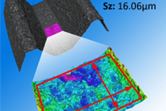
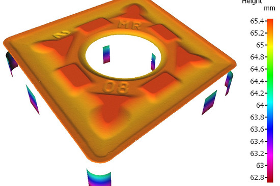
For round tools, chipping refers to the non-uniformity along the cutting edge. Let's call it the measure for micro deviations between target and actual geometry, i.e. an evaluation of the cutting edge topography. Note: Form deviations of the cutting edge do not count as chipping. As you can probably already imagine, a roughness measurement can provide information about this quality factor. And this should also be carried out, as the roughness has a direct influence on wear and tool breakage.

The flute must excel above all with its roughness values. This is the part of the tool that removes the chip. If this does not happen smoothly and the chip sticks to the drill bit or milling cutter, the result is that the drill bit becomes wedged because the chip is in the way during work. On the other hand, the chip heats up and even melts on the tool. It is probably self-explanatory that the machining quality suffers from such a heat build-up. Groove roughness also plays an important role for the coating.
With most coating processes, small defects - so-called droplets - appear on the flute. These in turn form a resistance to chip removal. There is also a risk that the coating will break at these points. Whether the droplets on your tool are within tolerance or not must also be determined by your quality assurance department. They may need to be smoothed out again.

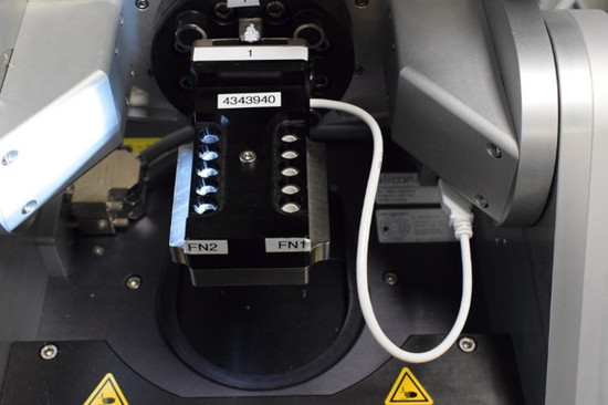
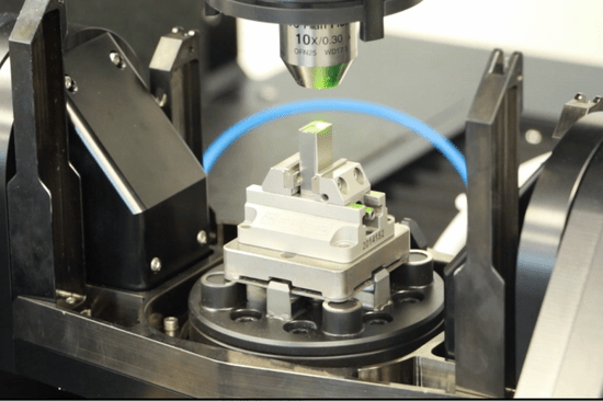
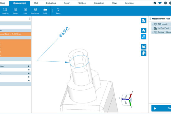
Have you found out what is really special about the new Round Tool Alignment? You no longer have to worry about the alignment of your tool, as this is recognized fully automatically. You simply clamp it and the rotary unit aligns the drill or milling cutter according to the CAD that you have loaded in advance. This has the following advantages:
There are many more parameters on your drills and milling cutters that you want to and should determine. These are:
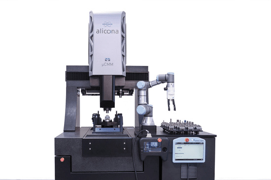
-533x300.jpg "different parameters of the tool can be inspected with only one Bruker Alicona measurement device")
This whitepaper gives you a deeper insight into the quality parameters of cutting tools.
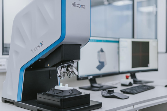
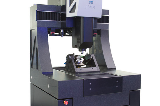
You need a Bruker Alicona measuring system if you want to meet the highest standards for your drills, milling cutters and countersinks. That may sound like a high purchase price at first. But the good news is that you only need a single device for all the parameters and measuring tasks mentioned above. The Round Tool Alignment is available for the MetMaX software, regardless of which of the following three measuring systems you work with.


Are you only interested in quick and easy measurements of cutting edges directly in production? Then take a closer look at our EdgeMaster series. Also available as a cobot for large cutting tools. And if you are not yet sure what exactly you need, then get in touch with us and we will find the best solution together.
dieSonne-web-(21)-550x366.jpg "Turbine Blade with Cooling Holes")


-550x366.jpeg)

die_Sonne-550x366.png "Bruker Alicona at AMB 2024 in Stuttgart")


_Nagel-550x366.jpg)
-1024x563-550x366.jpg)
dieSonne-065-868x397-550x366.jpg)

dieSonne-120-550x366.jpg)


dieSonne-137-550x366.jpg)

dieSonne-(10)-2076x1706-550x366.jpg)

dieSonne-web-(102)-550x366.jpg "Rotation and tilt unit Real3DUnitX")
-550x366.jpg "knee implant measurement")
dieSonne-(23)-1706x1708-550x366.jpg "Key Regions of Turned Parts, Stamped Parts, Round Tools measured")
dieSonne-(01)-2277x1706-550x366.jpg "Production Metrology")
