Quality Control of Cooling Holes in Aircraft Turbine Blades
Precisely manufactured cooling holes are crucial to prevent turbine failures and ensure the safe operation of an aircraft. These specially shaped cooling holes ensure that a cooling film is created along the turbine blades, which protects them from overheating. This ensures that your turbine runs efficiently and safely even at extreme temperatures.
But how do you ensure that each of the up to 500 cooling holes meets the high safety standards? Optical metrology supports you in the quality control of cooling holes: shape, surface roughness, angles and transitions are measured with micrometer precision and deviations are detected immediately. Discover how simple and automated measurement processes can reliably and safely bring your aircraft turbines to peak performance!
Measuring Cooling Holes: Simple, Fast, Automated
In the compressor of an aircraft engine, extreme temperatures prevail – ideal for greater efficiency and lower fuel consumption. But without the cooling holes in the turbine blades, the material would melt. These micro-holes are the key to protecting the turbine from overheating and ensuring a safe flight. Their exact position, orientation, shape and distribution make the difference between a smooth flight and potential turbine failure. During the quality control of the cooling holes, it is important to ensure that the angle, size and shape of up to 500 cooling holes, which may differ in form, correspond exactly to the CAD data.
dieSonne-web-(21)-600x400.jpg)
Turbine blade with cooling holes

3D data of a cooling hole
Different Shapes of Cooling Holes
Cooling holes can be categorized according to the following shapes:
- Diffuser hole
- Round hole
- Conical hole
- Long hole

Classification of cooling holes
The "All-in-One” Measurement Solution for Cooling Hole Inspection
The geometric inspection of cooling holes is one of the most challenging aspects of metrology. In addition to a technology that can measure the geometry and position of the cooling holes in relation to a reference system, there is a high demand for automation.
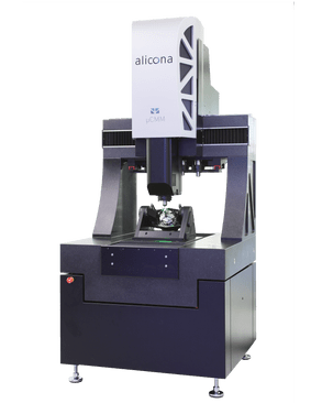
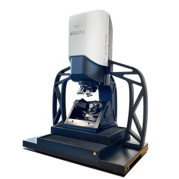
Bruker Alicona has a clear solution to determine all the parameters of the cooling holes. One measuring device - the µCMM - combines two technologies to obtain the desired measurement data. Vertical Focus Probing offers a fast, high-resolution and non-contact measurement of the bore geometry and allows to measure deep into the bore - even with flanks of up to 90°. This method ensures that each cooling hole is perfectly positioned for maximum cooling performance and safety. The surface, i.e. the conical part of the hole, is the task of the Advanced Focus-Variation. By using a lens with a super-large working distance of up to 130 mm, the user does not have the slightest restriction on accessibility.
The µCMM in combination with the MetMaX user software not only makes it possible to measure cooling holes, but also allows this complex application to be automated. First, the cooling hole is aligned so that it is perfectly centered in the live view. In the next step, the 3D measurement is performed and finally the relevant parameters are evaluated.

The "All-in-One"- optical measuring solution - the µCMM
Ready to Maximize the Safety and Efficiency of Your Aircraft Turbines?
"In addition to a technology that can measure the geometry and position of the cooling holes in relation to a reference system, the measurement of cooling holes requires a high demand for automation. We know measuring tasks where up to 500 different cooling holes at different positions should be verified. The µCMM is suitable for this measurement task."

More Solutions for Precise Turbine Engine Components

Break Edges
Burrs and sharp edges, which can occur during turning, milling or drilling, quickly lead to material fractures and dangerous cracks. Particularly for highly critical components such as fan blades, compressor disks, blisks or turbine housings, precise edge processing and reliable inspection methods are crucial. With optical metrology, you can capture even the smallest deviations in the µm-range quickly, in high resolution and with repeatable accuracy. This avoids expensive rework and ensures reliable turbine engine operation.

Defects
In turbine components like rotor blades, even small defects can compromise safety. Assessing the maximum defect depth is crucial for deciding if a part needs repair or replacement. Skimping on quality control risks cracks and heat build-up, potentially leading to critical failures. With Focus-Variation technology, you can accurately measure surface defects in 3D - capturing width, depth, and volume of cracks and scratches with high precision, ensuring your components remain safe and reliable.

Coating Processes
The coating of turbine blades not only increases wear resistance, but also directly influences performance. Crucial here: surface roughness before and after coating. Before coating, roughness ensures optimal adhesion; after coating, it influences aerodynamics. With optical metrology, you can precisely measure both layer thickness and roughness – for the best possible performance. Find out how optical metrology can make your blades more resilient and efficient!


